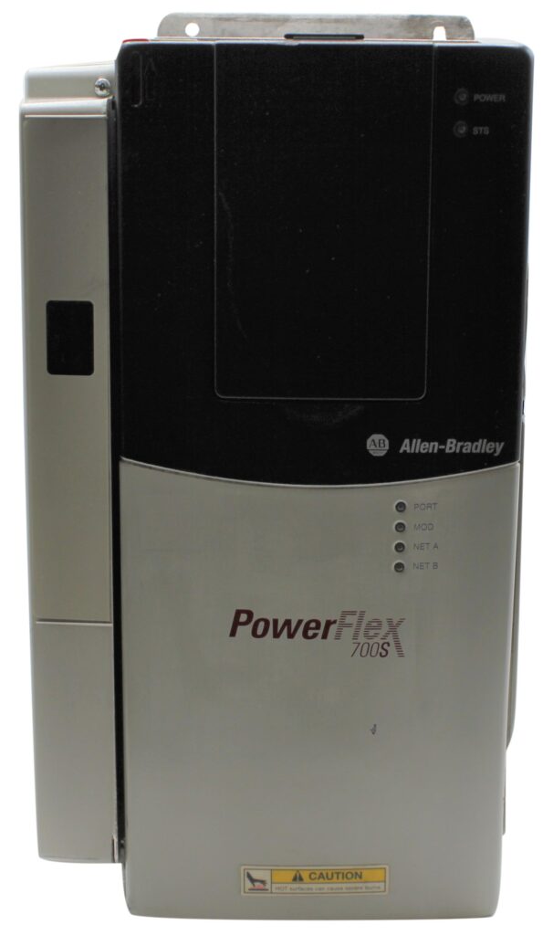
The PowerFlex 700S AC drive family supports Phase II control, leveraging DriveLogix software to combine the powerful Logix engine with high-performance PowerFlex AC drives, delivering a cost-effective control solution. In this article, we will be discussing the steps for a user to utilize the PowerFlex 700S AC drives. These drives offer various reset defaults for quick voltage/frequency setup, with power ratings that range from 50 to 1500 kilowatts at 690 Volts AC, 1 to 1600 Horsepower at 500 to 600 Volts AC, 1 to 1250 Horsepower at 380 to 480 Volts AC, and 1 to 100 Horsepower at 200 to 240 Volts AC. The drives operate with both 6-pulse and 3-phase input for full rating support, while single-phase input provides 50% of the rated current.
Configuration is flexible with an optional LCD HMI, remote keypad, and computer-based management tools. For high-speed data transmission and synchronization, PowerFlex 700S drives are equipped with SynchLink, a fiber-optic link, and offer optional modules for connectivity via serial, Ethernet, and ControlNet networks. They support various feedback options, such as incremental encoders, resolvers, and high-resolution encoders, with additional feedback interfaces for Stahl SSI and Temposonics devices. The drives support multiple motor control algorithms, including flux vector control, and are certified by ATEX, CE, C-Tick, and UL standards. Operating temperature ranges vary depending on enclosure type, with 0 to 50°C for open and IP 20-rated drives and 0 to 40°C for IP 56 and NEMA/UL Type 1 drives.
Mounting Clearances
Adherence to specified operating temperatures and accurate mounting clearances are crucial for the PowerFlex 700S series drives to operate at their best. Make sure there is enough room for airflow around the drive, following the user manual’s recommended clearances. This avoids overheating and encourages efficient cooling. A specific temperature range is ideal for the drives’ operation since variations beyond this might cause premature wear or hinder functioning. Verifying environmental management within these limitations is essential, especially for applications with high demand.
AC Supply Source and Power Conditioning
Stable drive functioning depends on selecting the right AC supply source while taking power quality into account. Grounding and input power conditioning are recommended to reduce harmonics and voltage spikes because unbalanced or ungrounded distribution networks might introduce abnormalities. While appropriate grounding lowers the possibility of electrical noise interfering with the system, the use of isolation transformers or line reactors aids in managing oscillations. This prolongs the life of the PowerFlex 700S drive in challenging conditions by guaranteeing dependable drive functioning.
Grounding and Shield Termination Requirements
Grounding for PowerFlex 700S drives must follow the recommended scheme for safe and stable operation, preventing electrical interference. Proper grounding mitigates the risks associated with stray voltage and static buildup and ensures compliance with regulatory standards. Shield termination (SHLD) and RFI filter grounding further help protect the drive from radio-frequency interference, a key consideration in high-frequency environments. Establishing these grounding and shielding practices supports operational safety and protects sensitive components against electrical disturbances.
Power Wiring, Cables, and Terminal Blocks
The operation of the drive depends on effective power wiring, which includes choosing the right cable types for installations involving 200–600V. Power terminal blocks are made for safe connections, and the handbook outlines the maximum motor cable lengths for the best signal transmission. Before installation, ensure all parts are accessible and seated correctly by removing the power wire access panels and cable entrance plate. Setting up AC input phase selection and checking cooling fan voltage are required for bigger frame drives to comply with operating requirements.
I/O Wiring and Configuration for Main Control Board
Proper I/O wiring on the main control board facilitates smooth integration with auxiliary systems. This includes configuring terminals and setting up hard-enabled circuitry for safety. Control board I/O configuration settings enable customized adjustments, such as auxiliary power supply integration and CE conformity adherence for compliance with low-voltage and EMC directives. LED indicators assist with status monitoring, while configuration supports precise control, making the PowerFlex 700S adaptable to complex industrial applications.
Preparing for Drive Start-Up
For a smooth start-up, it is essential to make sure all pre-power requirements are satisfied before turning on the PowerFlex 700S Series Drive. To avoid electrical risks, first, make sure that all wire connections are tight and properly grounded. Verify the working environment to make sure the humidity and temperature are within the advised ranges, and look for appropriate mounting clearances on the motor and drive. To avoid unbalanced or fluctuating supply problems, confirm input power conditioning with an AC source that is within the drive’s specified voltage and frequency limitations.
Initial Power Application and Assisted Start-Up
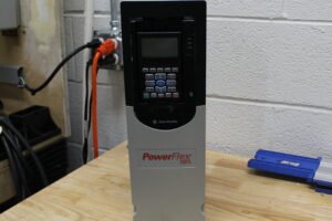
After the environment and wiring tests are finished, turn on the drive to initiate the startup process. Keep an eye out for any LED indicators on the control board that can indicate faults or readiness. Use the Assisted Start-Up feature, which offers detailed setting prompts, for convenience. Complete the drive’s first setup by calibrating important functions and configuring parameters such motor type, voltage levels, and control mode. This supervised procedure guarantees precise and safe drive operation, which is particularly advantageous for intricate drive applications.
Understanding PowerFlex 700S Drive Parameters
A wide range of settings on the PowerFlex 700S Series Drives enable exact control over drive performance and operations. The drive’s behavior, including fault reactions, torque control, and motor speed, is determined by parameters, which are programmable settings. Every element, from control modes to driving safety procedures, is intended for a certain operating aspect. By modifying these settings, the drive’s efficacy in intricate automation systems is increased, and optimal performance and flexibility for a range of industrial applications are guaranteed.
Organization of Parameters in the PowerFlex 700S Series
The PowerFlex 700S Series’s parameters are arranged methodically to make setting and navigation easier. To make setup and troubleshooting easier, parameters are categorized by function, such as motor control, diagnostics, and fault management. Users can find options more quickly because of the well-organized structure, which reduces configuration mistakes. Because each set of parameters is identified by a distinct code consisting of a number or letter, engineers may rapidly identify, modify, and fine-tune certain drive functions to satisfy the needs of the application.
Linear List and Cross-Reference for Parameter Identification
With the PowerFlex 700S’s linear list format, which shows all parameters consecutively, browsing options and confirming setups are simple. The Parameter Cross Reference By Name feature enables users to search parameters alphabetically for more focused navigation, making it possible to quickly access particular settings without knowing the numerical code. Drive programming and troubleshooting are made more efficient by this dual-format technology, which also allows for quick modifications and continuity across various operating needs.
Diagnosing Faults and Alarms on the PowerFlex 700S Drive
Faults and alarms are crucial markers of possible problems with the drive in the PowerFlex 700S Series. Critical problems, known as faults, which are frequently brought on by circumstances like overcurrent, overvoltage, or motor overheating, cause operations to stop. Contrarily, alarms serve as alerts of non-critical problems so that remedial measures can be taken before a shutdown. Maintaining maximum drive performance and avoiding extended downtimes in industrial applications requires careful observation and comprehension of these signs.
Analyzing Drive Status and LED Indications
Through LED indications and drive status indicators, the PowerFlex 700S Drive offers insightful information on operational conditions. Users are notified of the drive’s operating state by status indications, which include “Running,” “Stopped,” and “Faulted.” The LEDs provide visual indicators of many circumstances, including colors and flashing patterns. To ensure safe power startup, Precharge Board LED Indications particularly notify users of the precharge circuit state. Comprehending these signals facilitates prompt diagnostics, reducing the amount of time needed to find and fix problems.
Using HIM and Manual Fault Clearing
Rapid troubleshooting is made possible by the PowerFlex 700S’s Human Interface Module (HIM), which shows fault and alarm codes. On the module, HIM indicators give precise failure codes, explanations, and potential fixes. After resolving fundamental problems, users can additionally reset faults post-resolution by performing Manual Fault Clearing, which is essential for regaining drive performance. Furthermore, the malfunction Descriptions section offers thorough descriptions of every kind of malfunction, improving users’ capacity to troubleshoot efficiently and preserve the drive’s continuous, secure functioning.
Conclusion
In Conclusion, this user guide for the PowerFlex 700S Series Drives is designed to provide step-by-step assistance in maximizing the potential of these high-performance AC drives. From initial installation through setup, configuration, and fault diagnostics, each section offers comprehensive guidance for safe and efficient operation. The guide covers critical aspects, including precise wiring, grounding, and mounting clearances, essential for stable performance. It also walks users through startup procedures, including Assisted Start-Up and parameter configuration, ensuring accurate settings for motor type, voltage, and control mode. Detailed explanations of status indicators, LED signals, and the Human Interface Module (HIM) assist users in promptly diagnosing and manually clearing faults. By following this guide, users can confidently navigate the PowerFlex 700S, achieving reliable performance, robust control, and enhanced troubleshooting capabilities.
At Do Supply, we offer a full range of PowerFlex 700S models, ensuring you get the right drive for your system with expert support and fast shipping. Don’t let downtime or inefficient control hold your business back, call or email us today to secure your next PowerFlex 700S! We also have a blog comparing the different PowerFlex 7 series drives here.


Post Comment